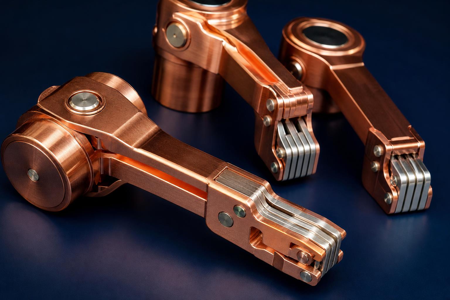
Understanding VCB Contact Arm Assemblies
When engineers talk about contact arm assemblies in medium-voltage vacuum circuit breakers, they are referring to two distinct but related components that are often confused:
- Internal contacts within the vacuum interrupter: The CuCr disc contacts inside the sealed vacuum chamber that actually interrupt the fault current. These are factory-sealed and cannot be serviced in the field — the entire vacuum interrupter is replaced when these contacts reach end of life.
- External contact arms on the withdrawable truck: The tulip-finger copper assemblies on the withdrawable carriage (手车) that plug into the fixed spout contacts in the panel cubicle when the breaker is racked in. These are accessible for inspection and replacement without replacing the vacuum interrupter itself.
This guide focuses on the external contact arm assemblies — the serviceable primary-circuit connection components — because these are the components most frequently requested by independent switchgear manufacturers and maintenance contractors as OEM spare parts. For vacuum interrupter replacement, see our guide: What Is a Vacuum Interrupter?
Contact Arm Design and Operating Principle
Tulip Contact Design
The most common external contact arm design for withdrawable VCBs is the tulip contact (also called a socket contact or plug-in contact). The assembly consists of:
- Contact fingers: A ring of 4–12 spring-loaded copper fingers, each individually flexible, arranged symmetrically around the contact axis
- Clamping spring: A circumferential coil spring or retaining clip that maintains a defined inward contact force (typically 80–150 N per finger for 630 A–2000 A assemblies)
- Current-carrying body: A solid copper barrel connecting the finger ring to the primary-circuit cable or busbar
- Insulating sleeve or housing: An epoxy or SMC molding that provides creepage distance and guides the contact into the spout
When the withdrawable truck is racked from the test position to the connected position, the contact fingers expand outward as the cylindrical pin of the fixed spout contact enters the tulip, then spring back to grip the pin with a defined contact force. This self-wiping action removes oxide film and ensures a reliable low-resistance connection with each racking cycle.
Moving Contact Assembly (动触头组件)
In some panel designs — particularly older VEP-pattern 12 kV panels common in the Middle East and South Asia — the moving contact assembly (动触头组件) refers to the complete assembly on the VCB truck that includes both the tulip contact fingers and the lower arm link connecting them to the VCB's primary terminal. This assembly moves vertically (in the racking direction) and also rotates slightly to accommodate manufacturing tolerances in the panel cubicle.
Replacement moving contact assemblies must replicate:
- The exact geometry of the finger ring (inner contact diameter, number of fingers, finger width)
- The link arm length and pivot point dimensions
- The total travel distance during racking
- The contact force at full engagement (verified with a contact force gauge)
Materials and Technical Specifications
| Parameter | Specification | Test Method |
|---|---|---|
| Base material | T2 electrolytic copper (Cu ≥ 99.9%) or C17200 beryllium copper for spring fingers | Material certificate |
| Silver plating thickness | ≥ 15 μm on contact surfaces (preferred: 20–25 μm) | XRF or cross-section metallography |
| Nickel undercoat | 2–5 μm (prevents Cu migration) | XRF or cross-section metallography |
| Silver hardness | HV 80–120 (fine-grained Ag) | Vickers micro-hardness |
| Contact resistance per phase | ≤ 50 μΩ (new); ≤ 100 μΩ (in-service limit) | IEC 62271-100, 100 A DC micro-ohmmeter |
| Contact force per finger | 80–150 N (specification-dependent) | Spring force gauge |
| Short-time current (1 s) | 20 kA or 25 kA (per rated assembly) | IEC 62271-100 type test |
| Temperature rise at rated current | ≤ 65 K above 40°C ambient (IEC 62271-1) | Temperature rise test |
Current Ratings and Selection
External contact arm assemblies are manufactured in standard current ratings corresponding to IEC 62271-1 preferred values. The correct rating must match the panel's rated normal current, not the VCB's rated current (the panel may be rated lower than the VCB).
| Rated Normal Current | Typical Finger Count | Finger Width | Contact Diameter Range |
|---|---|---|---|
| 630 A | 4–6 fingers | 12–15 mm | 35–45 mm |
| 1250 A | 6–8 fingers | 15–20 mm | 45–60 mm |
| 1600 A | 8–10 fingers | 18–22 mm | 55–70 mm |
| 2000 A | 10–12 fingers | 20–25 mm | 65–80 mm |
| 2500–4000 A | 12–16 fingers or dual-assembly | 22–30 mm | 80–120 mm |
Note: these are indicative ranges. Actual dimensions vary by manufacturer and panel design. Always provide a drawing or sample when ordering OEM replacements.
Ordering OEM Replacements from China
Information Required for Quotation
To receive an accurate quotation from a Chinese OEM manufacturer, provide:
- Rated normal current (e.g., 1250 A)
- Rated short-circuit current and duration (e.g., 20 kA / 1 s)
- Voltage class (12 kV, 24 kV, or 40.5 kV)
- Number of fingers and contact inner diameter (from drawing or measured sample)
- Contact arm total length and pivot geometry (from drawing)
- Silver plating specification (thickness and hardness class)
- Annual quantity and first-order quantity
- Mating fixed contact dimensions (pin diameter of the spout contact that engages the tulip)
From Sample to Production
If you have an original contact arm assembly but no drawing, a reputable Chinese OEM manufacturer can reverse-engineer from the sample:
- 3D scanning or manual measurement: All critical dimensions measured and recorded (1–2 days)
- Draft drawing created: Supplier produces dimensioned drawing for customer approval (3–5 days)
- Prototype production: First 3–5 pieces machined and plated (1–2 weeks)
- Customer validation: Dimensional check, contact resistance measurement, mechanical fit check on panel (customer's responsibility)
- Volume production: Approved drawing locked; production run within 3–4 weeks
Total time from sample receipt to first production delivery: typically 5–7 weeks.
Incoming Inspection and Acceptance Testing
When receiving OEM contact arm assemblies, perform the following acceptance tests before installation:
Dimensional Inspection
- Contact inner diameter at rest (no mating contact): check against drawing ±0.1 mm
- Finger count and symmetry: count fingers; check for equal spacing
- Overall assembly length: check against drawing ±0.5 mm
- Mounting hole/thread dimensions: verify fit on trial assembly before committing to production installation
Contact Resistance
Insert a calibrated pin (simulating the mating spout contact diameter) into the tulip and measure resistance between the pin and the contact arm back terminal at 100 A DC. New assemblies should read ≤ 30 μΩ. Reject anything above 50 μΩ as received.
Plating Quality
Visual inspection under 10× magnification: silver surface should be uniform, matte-bright, with no voids, blisters, or areas of base copper visible. Spot-check plating thickness with an XRF (X-ray fluorescence) gauge — minimum 15 μm on contact surfaces.
Contact Force
Insert a force gauge through the tulip axis and pull laterally against one finger. Multiply by finger count to estimate total contact normal force. Compare against the supplier's specified contact force (typically 300–900 N total for 630–2000 A assemblies). Low contact force indicates a fatigued or wrongly-specified spring.
NAIJI Electric VCB and Contact System Products
NAIJI Electric manufactures complete withdrawable vacuum circuit breakers including integrated contact arm assemblies for our VN-series indoor panels and ZW-series outdoor breakers. For independent panel assemblers requiring contact arms as standalone OEM components, we offer:
- Standard catalogue contact arm assemblies for common 630 A, 1250 A, and 1600 A ratings at 12 kV and 24 kV
- Custom contact arm assemblies from customer drawings or samples for VEP-compatible panel designs
- Complete withdrawable truck assemblies for 12 kV and 24 kV applications
- Full IEC 62271-100 type-test reports from independent laboratory
See our complete product range: VN series indoor VCBs | ZW32 and SPV outdoor VCBs. To discuss OEM contact arm supply, contact our engineering team →
Conclusion
Contact arm assemblies are high-wear, safety-critical components in withdrawable VCB switchgear. When sourcing OEM replacements from China, the key requirements are: exact dimensional match to the original (inner contact diameter, finger count, arm length), correct current and short-circuit rating, minimum 15 μm silver plating at HV 80–120, and a contact resistance below 50 μΩ as received. A qualified Chinese manufacturer can produce compatible assemblies from a drawing or sample in 5–7 weeks — at factory-direct pricing that is typically 40–60% below European OEM list prices.
The investment in a proper incoming inspection protocol — contact resistance measurement, dimensional check, and plating XRF — pays for itself by catching the occasional out-of-specification part before it enters service in a live switchgear panel.
Related reading: VEP Switchgear Components Supplier China | What Is a Vacuum Interrupter? | Vacuum Circuit Breaker vs SF6 Comparison