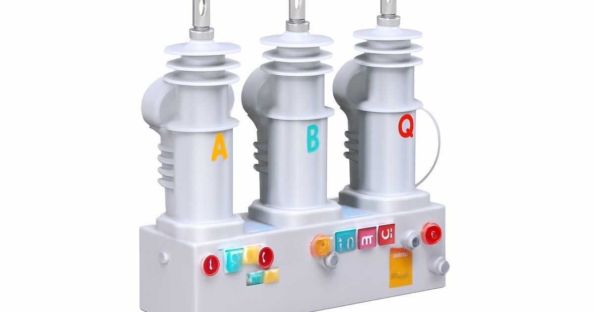
Quick Answer: The Breaker Protecting the Motor Is the Thing Damaging It
There is an uncomfortable symmetry at the heart of medium-voltage switching. Every property that makes a vacuum interrupter the right choice — dielectric recovery in microseconds, an arc that carries almost no energy, a contact gap of only 6-20 mm, 30,000 mechanical operations with no maintenance and no greenhouse gas — is the same property that makes it generate the fast-front overvoltages that destroy the load it is switching.
This is not a defect you can specify your way out of. A slower-recovering interrupter would not chop and would not restrike, but it would also not be a vacuum interrupter. The transient is intrinsic to the technology, which means surge protection is not an accessory to the breaker — it is the other half of the breaker, and it belongs in the same line of the bill of materials.
The practical consequences, up front:
- Modern CuCr contacts chop at 2-5 A, down from 10-15 A in older alloys — yet field failures did not disappear, because chopping is not the dominant mechanism.
- The damage is usually done by reignition and voltage escalation, and by virtual chopping across the three phases, both of which produce far worse numbers than a single-phase chop calculation predicts.
- The exposure is worst on short cables, not long ones — the opposite of most engineers' intuition.
- A surge arrester alone does not solve it. An arrester limits magnitude; only added capacitance limits dv/dt, and dv/dt is what stresses turn insulation.
Four Different Transients, Routinely Confused for One
Most published material collapses everything into "current chopping". In fact four distinct phenomena occur, with different causes, different waveshapes and different cures. Getting the diagnosis right determines which mitigation you buy.
| Mechanism | When it occurs | What drives magnitude | Typical front | What actually fixes it |
|---|---|---|---|---|
| Current chopping | Opening, at the first interruption attempt | Chop level x sqrt(L/C) of the load circuit | Slow, at load natural frequency (kHz) | Added capacitance (surge cap / RC) |
| Reignition & escalation | Opening, contacts still close together | Repeated re-strikes each raising trapped charge | 0.2-1 microsecond, repetitive | RC snubber (damps & slows recovery voltage) |
| Virtual current chopping | Opening, three-phase coupling after a reignition | Interphase capacitance of cable and winding | Very steep, high frequency | Three-phase RC at load terminals |
| Prestrike | Closing, gap breaks down before contact touch | Closing speed and instantaneous source voltage | Sub-microsecond, repetitive | Controlled/synchronous closing, RC snubber |
Note the pattern in the right-hand column. Three of the four are addressed by adding capacitance and damping at the load. Only one of them — and it is the mildest — responds to the chop level of the contact material that suppliers like to quote in their datasheets.
Why the Vacuum Gap Behaves This Way
A vacuum arc is not a gas arc. There is no gas to ionise; the conducting medium is metal vapour boiled off the contact surface by the arc itself. That creates a self-limiting feedback loop: as the current falls towards zero, the vapour production falls, the arc becomes unstable and at some low current it simply cannot sustain itself. That current is the chopping current, and it is a property of the contact material, not of the circuit.
| Contact material | Typical chopping current | Era / usage | Trade-off |
|---|---|---|---|
| CuBi (copper-bismuth) | ~5-15 A | Early vacuum interrupters | Low weld strength, higher chop |
| WCAg (tungsten-carbide-silver) | ~10-15 A | Contactors, low-chop duty historically | High chop, high erosion resistance |
| CuCr (chromium-copper) | ~2-5 A | Standard in modern MV VCBs | Best overall balance — today's default |
Contact-material chopping levels are representative ranges for medium-voltage interrupters; exact values depend on sintering process, contact geometry and axial magnetic field design.
The industry solved the chopping problem. It did not solve the restrike problem, because restrike is governed by a race between two curves: the transient recovery voltage rising across the gap, and the dielectric withstand of the gap growing as the contacts separate. At the instant of a late chop the contacts may be only a fraction of a millimetre apart. Vacuum recovers fast — roughly a few kilovolts per millimetre almost immediately — but the recovery voltage of a chopped inductive circuit rises faster still. The gap breaks down, current flows again, it is chopped again at a higher instantaneous value, and the load capacitance is charged to a higher level each time.
That escalation is bounded only by the contacts finally opening far enough. A sequence of tens to hundreds of reignitions in a few milliseconds is normal in a motor-switching event, and each one is a fresh steep-fronted pulse into the winding.
The Counter-Intuitive Part: Short Cables Are Worse
Ask an engineer which installation is more exposed — a motor on 30 m of cable or the same motor on 300 m — and most will say the long one, reasoning that longer cable means more chance of trouble. The physics says the opposite, for two independent reasons.
Reason one: impedance mismatch. A travelling wave arriving at the motor terminals sees a discontinuity. The surge impedance of a medium-voltage cable is low, typically in the region of 20-50 ohms. The surge impedance of a motor winding is high — commonly a few hundred ohms for a large machine and over a thousand for a small one. The reflection coefficient is (Zmotor - Zcable) / (Zmotor + Zcable), and when Zmotor is ten or twenty times Zcable that coefficient approaches +1. The reflected wave adds to the incident wave and the terminal voltage approaches double the travelling wave value.
| Cable surge impedance | Motor surge impedance | Reflection coefficient | Terminal voltage vs incident wave |
|---|---|---|---|
| 30 ohm | 150 ohm (large machine, ~5 MW) | +0.67 | 1.67x |
| 30 ohm | 500 ohm (mid-size, ~1 MW) | +0.89 | 1.89x |
| 30 ohm | 1,500 ohm (small machine, ~250 kW) | +0.96 | 1.96x |
Reflection coefficient = (Z2 - Z1) / (Z2 + Z1). Motor surge impedance rises as machine size falls, so smaller motors see reflection closer to full doubling.
Reason two: cable capacitance is free surge protection. The chopping overvoltage scales with sqrt(L/C). Three hundred metres of MV cable contributes a useful slab of C in parallel with the motor, lowering the surge impedance of the combined load and slowing the wavefront. Thirty metres contributes almost nothing. The long run partly protects itself; the short run does not.
The practical rule that falls out of this: a small motor on a short cable switched by a vacuum breaker is the worst case in the whole plant, and it is usually the one nobody specified protection for, because it did not look important enough.
What the Load Can Actually Withstand
Ground-wall insulation on a medium-voltage machine is generous, and it is not usually what fails. Turn-to-turn insulation is, and the reason is voltage distribution. Under a slow 50/60 Hz voltage rise, the potential divides itself more or less evenly along the winding. Under a front of a fraction of a microsecond, the inductance of the winding blocks the wave and the first few turns absorb a hugely disproportionate share — the classic non-linear initial distribution.
The relevant reference points:
- IEEE Std 522 — the guide for testing turn insulation of form-wound stator coils, applicable to machines from roughly 200 kW to 100 MW, specifies impulses with a rise time of 0.1 to 0.2 microseconds. Vacuum switching transients land squarely in that band.
- NEMA MG 1 Part 20 — addresses voltage stress on machine insulation from repetitive fast-front pulses, written for inverter duty but directly relevant to repetitive restrikes.
- IEC 60071 — insulation coordination, which governs how your surge arrester protective level relates to the equipment's rated withstand.
The failure mode is cumulative. A single 3 pu event with a steep front may not puncture anything. Several thousand of them, delivered a few hundred at a time every time the motor is started and stopped, will age the turn insulation until an ordinary event finishes it. This is why motors fail "for no reason" after years of uneventful service, and why the failure is almost always found in the first coil of a phase group at the line end.
Dry-type and cast-resin transformers sit in the same risk class for the same reason, with the added complication that they have no oil to provide self-healing or thermal margin. If your project specified a dry-type transformer for fire-safety reasons and a vacuum breaker for environmental reasons, you have combined the two most transient-sensitive choices available and you should assume protection is mandatory rather than optional.
Choosing the Mitigation: Magnitude vs dv/dt
There are only two things a protective device can do to a transient — reduce how high it goes, or reduce how fast it gets there. No single cheap device does both well. That is the whole of the selection problem.
| Device | Limits peak? | Limits dv/dt? | Typical values | Where it belongs | Relative cost |
|---|---|---|---|---|---|
| MOV surge arrester only | Yes | No | Per IEEE C62.11 / IEC 60099-4, MCOV above system Ug | Station and feeder, general duty | Low |
| Surge capacitor only | No | Yes | 0.1-0.5 microfarad per phase | Rarely used alone — resonance risk | Low-medium |
| Arrester + surge capacitor | Yes | Yes | Arrester + 0.1-0.5 microfarad | Transformers, generators | Medium |
| RC snubber (+ arrester) | With arrester | Yes, plus damping | ~0.1-0.25 microfarad in series with ~20-50 ohm | MV motors, frequently switched loads | Medium-high |
| Synchronous / controlled switching | Prevents rather than limits | Prevents | Point-on-wave controller with the breaker | Capacitor banks, reactors, large transformers | High |
Component values are the ranges commonly encountered in MV practice; final values must come from a study of the specific circuit. Guide-form RC snubber specifications for MV service reference UL 347, UL 508 and ANSI C37.20.2 for the enclosure, with integral arresters to ANSI/IEEE C62.11.
The distinction people get wrong most often: an arrester does nothing until the voltage exceeds its protective level. A 1.5 pu transient with a 0.2 microsecond front passes an arrester untouched and still tears the front turns of a winding apart, because the damage is done by the gradient, not the peak. Conversely, a bare surge capacitor slows the front beautifully and then sits in series with the source inductance forming a resonant circuit that can amplify a different frequency. The resistor in the RC snubber is what makes the combination behave.
For an integrated solution, so-called ZORC units combine a zinc-oxide element, a resistor and a capacitor in one three-phase enclosure sized for the motor terminal box. They are the pragmatic answer when the alternative is asking a site crew to assemble three separate devices with short leads in a space that was never designed for them.
Installation Rules That Decide Whether It Works
Surge protection is unusually sensitive to how it is mounted, because the device is competing against the inductance of its own connections.
- Mount at the load, not the switchgear. The overvoltage is created by reflection at the load terminals. Protection at the far end of the cable protects the cable.
- Keep leads under one metre and make them flat. Round conductor runs at roughly 1 microhenry per metre. At a di/dt typical of a restrike discharge, a metre of lead can develop a voltage comparable to the residual voltage of the arrester you are relying on — it does not merely reduce the benefit, it can halve it.
- Bond to a single point. The arrester earth, the RC earth and the motor frame must be at the same potential during the event. Separate earth paths turn a common-mode transient into a differential one across the machine.
- Protect both ends of a transformer where both sides are switched. A transient injected on the MV side is transferred capacitively to the LV side; the turns ratio does not attenuate a fast front the way it attenuates power frequency.
- Re-check after any cable change. Shortening a feeder during a plant modification can move a formerly quiet circuit into the worst-case band described above.
Copy-Paste Wording for Your Specification
Most transient problems are contractual before they are technical: the breaker scope and the motor scope are bought from different suppliers, and surge protection falls into the gap between them. This wording closes it.
"Vacuum circuit breakers and vacuum contactors supplied under this contract shall be classified in accordance with IEC 62271-100 with mechanical endurance class M2, electrical endurance class E2, and restrike class C2 where capacitive switching duty is present. The contact material and its representative chopping current shall be declared.
For every circuit in which a vacuum interrupting device switches a rotating machine, a dry-type or cast-resin transformer, a reactor or a generator, the Supplier shall include three-phase surge protection comprising a metal-oxide surge arrester to IEC 60099-4 or ANSI/IEEE C62.11 together with a damped capacitive element (RC snubber or equivalent), rated for the system voltage and mounted at the load terminals with connection leads not exceeding 1 m.
The Supplier shall submit a transient study, or documented equivalent engineering justification, for any circuit in which the connecting cable between the interrupting device and the load is shorter than 100 m."
That last clause is the one that earns its keep. It puts the burden of proof on the party who knows the equipment, and it triggers exactly on the short-cable condition that produces the worst reflections.
What We Control at the Factory — and What We Cannot
Being candid about the boundary is more useful to a buyer than a claim of immunity.
What the manufacturer controls: contact material and therefore chopping level; contact geometry and the axial magnetic field design that keeps the arc diffuse and reduces late-arc instability; closing and opening velocity characteristics, which set how much time the gap has to grow before the recovery voltage arrives; the restrike classification (C1 or C2) that we verify by type test; and whether a controlled-switching device can be integrated with the operating mechanism. Every vacuum circuit breaker and vacuum contactor we build uses CuCr contacts with axial magnetic field electrodes for exactly these reasons.
What the manufacturer does not control: the length and type of your cable, the surge impedance of your machine, whether the motor is started twice a day or forty times, and whether anybody mounted an RC unit in the terminal box. Those determine the outcome far more strongly than the breaker datasheet does.
Which is why our answer to "does your breaker cause switching transients?" is: yes, and so does everyone else's, because that is what a vacuum interrupter is. The right question is whether the circuit as a whole has been engineered for it. When a customer sends us a single-line with motor ratings and cable lengths at RFQ stage, we can flag the at-risk circuits before the order is placed — see our MV switchgear specification and RFQ guide for what to send.
Ten-Minute Screening Checklist
Run this over an existing single-line diagram. Any circuit collecting three or more marks needs a study or protection by default.
| Condition | Why it raises risk |
|---|---|
| Load is a motor, generator, reactor or dry-type transformer | Inductive, low capacitance, sensitive turn insulation |
| Cable between breaker and load is under 100 m | Low cable capacitance, high reflection coefficient |
| Machine rating below about 3 MW | Higher winding surge impedance, closer to full doubling |
| More than roughly one switching operation per day | Cumulative turn-insulation ageing dominates |
| Breaker or contactor may trip during starting | Interrupting locked-rotor current is a severe chopping case |
| No surge device present in the motor terminal box | Protection at the switchgear end does not control terminal voltage |
| Existing arrester but no capacitive element | Peak limited, dv/dt unlimited — the damaging part is unaddressed |
Related Technical Guides
- What Is a Vacuum Interrupter? — contact materials, axial magnetic field design and how the arc is actually extinguished.
- Vacuum Circuit Breaker vs SF6 — the ten-dimension comparison, including recovery behaviour.
- IEC 62271 Standards Guide — where M, E and C classification comes from and what the type tests prove.
- MV Motor Control: VFD vs Soft Starter vs Contactor — the upstream decision that sets your switching frequency.
- Vacuum Interrupter Testing Checklist — verifying interrupter condition in service.
Get the Circuit Reviewed Before You Order
NAIJI Electric manufactures medium-voltage vacuum circuit breakers, indoor VCBs, vacuum contactors and complete MV switchgear assemblies from 12 kV to 40.5 kV, with CuCr axial-magnetic-field interrupters, declared chopping performance and C2 restrike classification where the duty requires it. Typical lead time is 30-60 days, factory direct.
Send us your single-line with motor ratings and cable lengths and we will mark the circuits that need surge protection before they become warranty claims. Request a quote or talk to our engineering team.