Quick Answer: Choosing Your MV Distribution Topology
A medium voltage power distribution system carries power from the utility supply point to distribution transformers inside your facility at 1-52 kV. The single decision that drives cost, reliability and switchgear count is the topology. Four schemes cover almost every project: simple radial (cheapest, single point of failure), primary loop (+25-40% cost, restoration in minutes), primary selective (+15-25% cost, transfer in seconds), and secondary selective (+50-90% cost, near-zero interruption). Pick the cheapest scheme whose worst-case outage duration your process can actually tolerate — then size the switchgear lineup around it.
What a Medium Voltage Distribution System Actually Consists Of
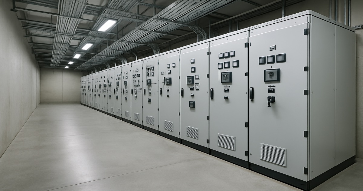
Engineers use "medium voltage electrical system" loosely, so it helps to be precise about the boundaries. In a typical industrial or commercial installation the MV system starts at the utility metering point and ends at the LV terminals of the distribution transformers. Between those two points sit five element types:
- Incoming switchgear — one or two incomer bays containing a circuit breaker, current and voltage transformers, metering and the main protection relay. This is where the utility hands over.
- Busbar system — the copper or aluminium bus running the length of the lineup, rated 630 A to 5000 A. A bus coupler bay splits it into two sections that can be operated independently.
- Feeder bays — one per outgoing circuit, each with a circuit breaker or load break switch plus fuse, feeding a transformer, a motor, a capacitor bank or a downstream substation.
- MV cables — usually XLPE-insulated single-core or three-core, sized per IEC 60287 for continuous current and per IEC 60949 for short-circuit thermal withstand.
- Distribution transformers — 400 to 2500 kVA oil-immersed or cast-resin units stepping 12/24 kV down to 400/415 V.
If you are still fixing the voltage boundaries themselves, start with our primer on what medium voltage means and the standard voltage classes.
The Two Numbers That Govern Everything
Before topology, before switchgear selection, two figures must be established. Get them wrong and every downstream decision is wrong too:
- Maximum demand (MVA) — total connected load times diversity factor. For mixed industrial loads, diversity is typically 0.7-0.85. This sizes the busbar, incomer and transformers.
- Prospective short-circuit current (kA) — calculated per IEC 60909 from the utility fault level at the point of common coupling plus any on-site generation contribution. This sizes the breaking capacity of every circuit breaker and the short-time withstand of the busbar. Our short-circuit rating calculation guide walks through the arithmetic.
Ask your utility for both in writing. In our experience roughly one project in four arrives at the factory with a fault level that was assumed rather than confirmed, and a 25 kA lineup then has to be re-quoted at 31.5 kA — an 8-12% price increase and four extra weeks of lead time.
The Four MV Distribution Topologies Compared
Every practical MV network is one of four schemes or a hybrid of two. The differences come down to how many independent paths exist between the source and the load, and how quickly you can switch between them.
| Topology | Sources | Restoration Time | Relative MV Cost | Typical MV Bay Count (10 MW plant) | Best For |
|---|---|---|---|---|---|
| Simple radial | 1 | Hours (repair time) | 100% (baseline) | 6-8 bays | Warehouses, light manufacturing, single-shift plants |
| Primary loop / ring | 1-2 | 5-30 min (manual), <60 s (automated) | 125-140% | 10-14 bays + RMUs | Campuses, distributed loads, urban networks |
| Primary selective | 2 | 1-10 s (auto) / 2-5 min (manual) | 115-125% | 10-13 bays | Continuous process, hospitals, cold storage |
| Secondary selective | 2 | <1 s with fast transfer | 150-190% | 12-16 bays + 2× transformer capacity | Data centres, semiconductor fabs, critical utilities |
1. Simple Radial
One incomer, one bus, feeders radiating out to each transformer. Power flows in exactly one direction, and protection coordination is straightforward because there is only one path for fault current. It is the cheapest scheme per delivered kVA and remains the correct answer for most industrial sites.
The weakness is obvious: a fault on the incomer cable, the main breaker or the busbar takes down the whole facility until it is repaired, which for a damaged MV cable joint means 4-24 hours. A partial mitigation that costs very little is to split the bus with a bus coupler bay and feed critical and non-critical loads from opposite sections, so a busbar fault only kills half the plant.
2. Primary Loop (Ring) System
Loads are connected around a closed ring of MV cable, with one switching point kept normally open so the ring actually operates radially. Each tap point uses a ring main unit — two load break switches for the through-ring cables and one breaker or switch-fuse for the transformer tee-off.
When a cable section faults, the two RMUs bounding it are opened, the normally-open point is closed, and everything except the faulted section is re-energized. With manual switching that is a 5-30 minute exercise depending on how far apart the substations are. With motorized RMUs and a fault passage indicator scheme, the same sequence runs automatically in under a minute.
The ring is the standard architecture for urban utility distribution and for campus-scale sites — universities, airports, industrial parks — where loads are spread over hundreds of metres and the additional cable run is unavoidable anyway.
3. Primary Selective System
Each transformer is fed from two independent MV feeders through a duplex switch or a pair of mechanically interlocked load break switches. One feeder is designated preferred, the other alternate. Loss of the preferred feeder triggers a transfer.
Compared with a loop, the primary selective scheme buys faster restoration (seconds rather than minutes) at a slightly lower cost, because the switching intelligence sits at each transformer instead of requiring a full closed ring of cable. It does not, however, protect against failure of the transformer itself — for that you need the secondary selective scheme.
4. Secondary Selective System
Two transformers, each on its own MV feeder, feed two LV bus sections joined by a normally-open LV tie breaker. Lose either feeder or either transformer and the tie closes, putting the whole load on the surviving transformer.
This is the most expensive scheme because both transformers must be sized for 100% of the combined load — you are buying 200% of the transformer capacity you actually need. It is also the only common industrial scheme that survives a transformer failure without an outage, which is why it dominates in data centres and pharmaceutical plants.
Design rule of thumb: if your process can tolerate a 30-minute outage, use radial with a bus coupler. If you need restoration in minutes, use a loop. If you need seconds, use primary selective. If you need essentially none, use secondary selective and accept the doubled transformer cost.
Mapping the Topology onto a Switchgear Lineup
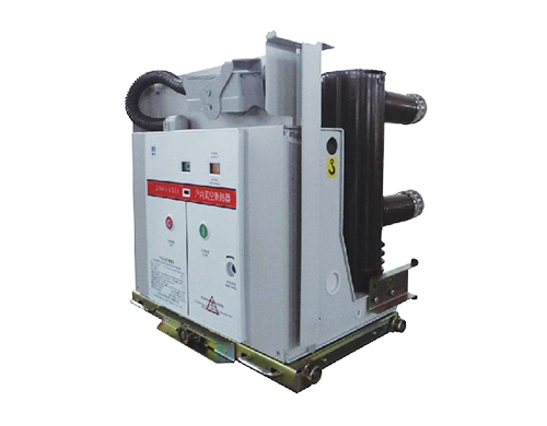
Once the topology is chosen, the lineup almost writes itself. Every scheme is assembled from the same five bay types, and a manufacturer quotes per bay, so counting bays is how you get a budget number quickly.
| Bay Type | Main Device | Typical Rating | Indicative FOB Price (12 kV) | Purpose |
|---|---|---|---|---|
| Incomer | Vacuum circuit breaker + CT/VT + metering | 1250-3150 A | $4,500 - $9,000 | Utility handover, main protection, revenue metering |
| Bus coupler | Vacuum circuit breaker | Matched to bus | $3,500 - $7,000 | Splits busbar into two independently operable sections |
| Transformer feeder | VCB or switch-fuse | 630-1250 A | $2,800 - $6,500 | Feeds one distribution transformer |
| Motor feeder | Vacuum contactor + fuse | 400-630 A | $3,000 - $6,000 | Frequent switching duty for motors >200 kW |
| Metering / VT bay | Voltage transformers + surge arrester | - | $2,000 - $4,000 | Bus voltage reference, synchronizing, PQ monitoring |
Prices above are indicative FOB China ranges for air-insulated 12 kV metal-enclosed switchgear at 31.5 kA, and vary with current rating, internal arc class and relay specification. For the internal layout of each bay type — compartmentation, shutters, cable termination space — see our switchgear lineup design guide.
A Worked Example: 10 MW Industrial Plant
Take a plant with 10 MW maximum demand at 11 kV, four 2500 kVA distribution transformers, two 1 MW MV motors, and a utility fault level of 25 kA. A primary-selective design produces this lineup:
- 2 × incomer bays (one per utility feeder), 2000 A, 25 kA
- 1 × bus coupler bay with automatic transfer logic
- 4 × transformer feeder bays, 630 A
- 2 × motor feeder bays with vacuum contactors
- 2 × metering / VT bays (one per bus section)
- 2 × spare feeder bays for future expansion
That is a 13-bay lineup, roughly 13 m of switchroom wall at 1000 mm depth, at an indicative equipment cost of $48,000-$95,000 FOB. Specifying a compact design such as the ASN550 at 550 mm depth reclaims 30-45% of the room depth, which regularly decides whether an existing switchroom can be reused in a retrofit.
Selecting the Distribution Voltage
Where the utility gives you a choice — or where you are designing an internal distribution level below the incoming supply — the voltage decision trades cable cost against switchgear cost.
| Class | System Voltage | BIL | Economical Load Range | Economical Cable Run | Relative Bay Cost |
|---|---|---|---|---|---|
| 7.2 kV | 6.6 kV | 60 kV | Up to 10 MVA | < 1.5 km | 0.9× |
| 12 kV | 10-11 kV | 75 kV | Up to 25 MVA | < 3 km | 1.0× |
| 24 kV | 20-22 kV | 125 kV | 25-60 MVA | 3-10 km | 1.4× |
| 36 kV | 33 kV | 170 kV | 60-120 MVA | 10-25 km | 1.7× |
| 40.5 kV | 35 kV | 185 kV | 60-150 MVA | 10-30 km | 1.8× |
Doubling the voltage halves the current for the same power, which cuts I²R losses by a factor of four and lets you use a much smaller cable cross-section. Against that, the switchgear needs larger clearances: a 24 kV bay is typically 200-300 mm wider and deeper than the 12 kV equivalent, and a 40.5 kV bay wider again. The crossover where higher voltage pays back is usually around 25 MVA or 3 km of cable, whichever comes first.
Protection Coordination Across the System
A distribution system that trips the main incomer for a fault on one small feeder is not a distribution system, it is a single large circuit. Selectivity — the property that only the breaker closest to a fault operates — is what keeps a topology's reliability promise intact.
The standard industrial scheme uses three coordinated layers:
- Feeder protection — instantaneous overcurrent (ANSI 50) plus inverse-time overcurrent (51) and earth fault (50N/51N), set to clear feeder faults in 0.1-0.3 s.
- Bus / bus coupler protection — same functions with a 0.3-0.4 s grading margin above the feeders, or a fast busbar blocking scheme where downstream relays inhibit the incomer trip.
- Incomer protection — overcurrent graded 0.3-0.4 s above the bus layer, plus directional elements (67) where two sources can feed the same bus.
Grading margins of 0.3-0.4 s per level are conventional for electromechanical-era coordination; with modern numerical relays and IEC 61850 GOOSE blocking you can hold the margin to 0.15-0.2 s, which meaningfully reduces arc-flash incident energy at the busbar. IEEE 242 (the Buff Book) is the standard reference for the coordination study itself, and our protection relay guide covers the ANSI function codes in detail.
Practical point from the factory floor: supply your relay manufacturer and model to the switchgear builder before production, not after. Retrofitting a different relay family into a finished bay means re-cutting the door aperture, rewiring the CT circuits and re-testing — typically two to three weeks of added lead time.
Six Design Mistakes We See Most Often
Across the switchgear lineups we build each year for export projects, the same specification errors recur. Each one is cheap to fix at the drawing stage and expensive to fix afterwards.
- No spare bays. Every lineup fills up. Adding two spare feeder bays at build time costs roughly 60% of what a later field extension costs, and avoids an outage to make the busbar connection.
- Busbar sized for today's load. The busbar is the one component you cannot upgrade without replacing the whole lineup. Size it for the ultimate site demand, not the phase-one demand.
- Assumed fault level. Get the utility's prospective short-circuit current in writing. Under-rated breaking capacity is a safety defect, not a commercial one.
- Ignoring altitude derating. Above 1000 m, external insulation withstand falls by roughly 1% per 100 m per IEC 62271-1. A site at 3000 m needs equipment specifically qualified for it — our ASN3-12 is rated to 4500 m without derating.
- Cable termination space underestimated. Three single-core 300 mm² XLPE cables per phase need far more room and bending radius than the drawing usually allows. Confirm the cable schedule with the switchgear builder before the bay depth is frozen.
- No internal arc classification. Where personnel work in front of energized switchgear, specify an IAC class per IEC 62271-200 Annex A (for example IAC AFLR 31.5 kA 1 s) and state which sides are accessible. It is a specification line item, not an afterthought.
MV Distribution Design Checklist
Before issuing an enquiry to a switchgear manufacturer, have these twelve items settled. A complete data set is the single biggest determinant of quotation accuracy and lead time:
- Rated voltage and system voltage (e.g. 12 kV rated, 11 kV system)
- Frequency (50 or 60 Hz)
- Maximum demand in MVA, present and ultimate
- Prospective short-circuit current in kA and duration (1 s or 3 s)
- Topology and single-line diagram
- Bay schedule: type, quantity, rated current per bay
- Neutral earthing method (solid, resistance, resonant, isolated)
- Internal arc classification and accessible sides
- Installation environment: indoor/outdoor, altitude, ambient range, humidity, pollution level
- Protection relay make and model, and communication protocol (IEC 61850, MODBUS, DNP3)
- Cable type, size and number per phase, with entry direction (top or bottom)
- Applicable standard: IEC 62271-200, IEEE C37.20.2/3, GB 3906, or a national derivative
How NAIJI Supports MV Distribution Projects
NAIJI Electric manufactures the complete MV equipment range needed to build any of the four topologies above: air-insulated metal-enclosed switchgear from 12 kV through 40.5 kV, SF6-free gas-insulated switchgear for space-constrained substations, indoor vacuum circuit breakers, outdoor pole-mounted breakers for ring feeders, and low-voltage switchgear for the secondary side.
All switchgear is type-tested to IEC 62271-200 at accredited laboratories, with annual production capacity above 3,000 bays. Standard 12 kV configurations ship in 4-6 weeks; project-specific lineups in 8-12 weeks.
For projects still at the design stage, our engineering team reviews single-line diagrams, checks bay schedules against the stated fault level, and returns a bay-by-bay proposal — typically within three business days.
Frequently Asked Questions
What is a medium voltage power distribution system?
It is the network of switchgear, cables and transformers carrying power between the utility supply point and the low-voltage loads, operating at 1-52 kV per IEC 62271-1. It comprises incoming switchgear, a busbar system, feeder bays, MV cables and MV/LV distribution transformers.
What is the difference between a radial and a loop distribution system?
A radial system supplies each load through a single path, so a fault on that path causes an outage until repair. A loop system connects loads in a closed ring with one normally-open point; after a cable fault, operators transfer the open point to restore supply in 5-30 minutes manually or under 60 seconds with automated ring main units. A loop costs 25-40% more in MV equipment.
How many MV feeders should a facility have?
A working rule: one feeder per distribution transformer, one per motor above 200 kW, plus one spare bay for every four loaded bays. A 10 MW plant with four transformers and two large motors therefore needs about six loaded feeders, two spares, two incomers and a bus coupler — a 13-bay lineup.
How do I size a distribution transformer?
Take maximum demand, apply a diversity factor of 0.7-0.85 for mixed industrial load, add 20-25% growth margin, then round up to the next standard rating (400 / 630 / 1000 / 1250 / 1600 / 2000 / 2500 kVA). Avoid sustained loading above 80% of nameplate; IEC 60076-7 gives the loading guide. In a secondary selective scheme, size each transformer for 100% of the combined load.
When is a primary selective system worth the extra cost?
It adds roughly 15-25% to MV equipment cost and cuts restoration from hours to seconds. It pays back when an unplanned outage costs more per hour than the added capital amortized over plant life — typically continuous-process industry, hospitals, cold storage and data centres.
Which standards apply to MV distribution design?
IEC 62271-200 (metal-enclosed switchgear), IEC 62271-100 (circuit breakers), IEC 60909 (short-circuit calculation), IEC 60076 (transformers), IEC 60287 (cable rating) and IEC 61936-1 (installations above 1 kV). North American equivalents: IEEE C37.20.2/C37.20.3, IEEE 141, IEEE 242 and NFPA 70E.
Can I extend an existing MV switchgear lineup later?
Yes, if the original lineup was built with an extendable busbar end and the extension bays match the original design, ratings and manufacturer. In practice a field extension costs roughly 1.7× the price of ordering the same bays at build time and requires a shutdown to make the busbar joint — which is why we recommend specifying spare bays up front.
Get a Bay-by-Bay Proposal for Your Project
Send us your single-line diagram, or simply the bay schedule and fault level, and our engineering team will return a bay-by-bay technical and commercial proposal.
What to include in your enquiry:
- System and rated voltage, frequency
- Maximum demand (present and ultimate)
- Prospective short-circuit current and duration
- Topology and number of bays by type
- Installation environment: indoor/outdoor, altitude, ambient temperature
- Protection relay preference and communication protocol
Request an MV Distribution Proposal →
Related guides: What Is Medium Voltage? | Switchgear Lineup Design | Short-Circuit Rating Calculation | MV Switchgear Types & Selection | Ring Main Unit Guide | Protection Relay Guide