Quick Answer: Your Site Probably Is Not "Normal"
IEC 62271-1 defines normal service conditions for indoor switchgear as relative humidity and water vapour pressure not exceeding 95% and 2.2 kPa averaged over 24 hours, and 90% and 1.8 kPa averaged over a month. Every catalogue rating, every type test and every warranty you are quoted assumes those conditions.
Here is the trap. Those are two independent limits, and in a hot climate the vapour-pressure limit bites long before the humidity limit does:
- 2.2 kPa is 95% RH at 20 degC — which is exactly where the number in the standard comes from.
- At 30 degC, 2.2 kPa is reached at 52% RH.
- At 35 degC, it is reached at 39% RH.
- The monthly limit of 1.8 kPa is reached at 30 degC and only 43% RH.
A switchroom in Jakarta, Lagos, Manila, Chennai, Guayaquil or Douala is outside IEC 62271-1 normal service conditions on essentially every day of the year, usually by a wide margin, while the humidity figure on the site data sheet looks perfectly ordinary. Specifying "IEC 62271-200, IP4X, tropicalised" does not fix this, because none of those declarations addresses condensation.
What does address it is IEC TS 62271-304, a technical specification most buyers have never heard of and most suppliers never offer. The rest of this article covers what it classifies, what the test actually involves, the one thing it explicitly cannot certify, and what to do about the gap.
The Vapour-Pressure Trap, in Full
Relative humidity is a ratio, not a quantity. It tells you how close the air is to saturation at its current temperature, and it tells you nothing about how much water is actually present. Water vapour pressure is the absolute measure, and it is what determines how much condensate forms on a surface when the temperature drops.
The table below is computed from the Magnus saturation-vapour-pressure relation and compared against the two IEC 62271-1 limits.
| Air temperature | Saturation vapour pressure | Vapour pressure at 95% RH | RH that hits the 24-h limit (2.2 kPa) | RH that hits the monthly limit (1.8 kPa) |
|---|---|---|---|---|
| 15 degC | 1.70 kPa | 1.62 kPa | not reachable | not reachable |
| 20 degC | 2.33 kPa | 2.22 kPa | 94.3% | 77.1% |
| 25 degC | 3.16 kPa | 3.00 kPa | 69.6% | 56.9% |
| 28 degC | 3.77 kPa | 3.59 kPa | 58.3% | 47.7% |
| 30 degC | 4.24 kPa | 4.03 kPa | 51.9% | 42.5% |
| 32 degC | 4.75 kPa | 4.51 kPa | 46.3% | 37.9% |
| 35 degC | 5.62 kPa | 5.34 kPa | 39.2% | 32.0% |
| 40 degC | 7.38 kPa | 7.01 kPa | 29.8% | 24.4% |
Saturation vapour pressure computed from the Magnus formula. IEC 62271-1 normal service condition limits for indoor switchgear: 95% RH and 2.2 kPa over 24 hours; 90% RH and 1.8 kPa over one month.
Read the 20 degC row first: 95% RH gives 2.22 kPa, which is the standard's own limit to two significant figures. That confirms the standard was written around a 20 degC reference. Now read the 35 degC row. At the tropical norm the limit is breached at 39% relative humidity — a reading that would look bone dry on a site survey.
The practical consequence: below about 25 degC ambient, the RH limit is the binding one and you can reason about humidity in the familiar way. Above about 28 degC, the vapour-pressure limit is binding and relative humidity becomes actively misleading as a specification parameter. If your site runs hot, stop quoting RH to your supplier and quote absolute humidity or dew point instead.
How Condensation Actually Destroys Insulation
Condensation on its own is not very dangerous. Pure water on clean epoxy is a mediocre conductor, and a well-designed creepage path will tolerate a film of it. The destruction comes from a four-stage sequence that needs both moisture and deposits:
- Deposition. Dust, cement, salt aerosol, diesel soot or industrial residue settles on insulating surfaces over months. In a sealed, filtered switchroom this stage never happens and nothing that follows happens either.
- Wetting. A temperature swing — a night-to-day transition, a load change, a ventilation fan starting, a door opened in the rainy season — drops a surface below the dew point. The condensate dissolves the deposits into a conductive electrolyte film bridging the creepage path.
- Dry-band formation. Leakage current flows and heats the film. It dries unevenly, leaving narrow dry bands that now carry almost the entire voltage drop across a few millimetres. Small surface arcs strike across them.
- Tracking. Each arc carbonises a little polymer. Carbon is permanent and conductive. The effective creepage distance shortens with every cycle until a flashover occurs at normal operating voltage.
The timescale is the reason this is such an under-managed risk. The equipment passes every commissioning test, works perfectly for two to five years, and then fails without an obvious trigger. By then the warranty has expired and the failure gets logged as a product defect rather than as a service-condition problem. Our switchgear maintenance and testing guide covers the inspection intervals that catch stage 3 before it becomes stage 4.
Stage 1 is the controllable one, and it is why the classification described next is conditioned entirely on pollution level.
IEC TS 62271-304: The Classification Nobody Specifies
IEC TS 62271-304:2019, Edition 2.0 covers the classification of indoor enclosed switchgear and controlgear for rated voltages above 1 kV up to and including 52 kV, for use in special service conditions with respect to condensation and pollution deviating from the normal service conditions of IEC 62271-1. It applies to equipment built to IEC 62271-200 (metal-enclosed) and IEC 62271-201 (solid-insulation-enclosed).
It defines the environment in two dimensions.
| Code | Condensation environment | Typical room |
|---|---|---|
| C0 | Condensation does not normally occur — not more than twice a year | Rooms with continuous humidity or temperature control; or uncontrolled rooms where the building still buffers daily outdoor swings well enough that condensation happens at most twice a year |
| CL | Non-frequent condensation — not more than twice a month | Rooms without humidity or temperature control, where the building buffers daily variation but condensation cannot be excluded |
| CH | Frequent condensation — more than twice a month | Rooms with neither humidity nor temperature control, where the building gives only minimal protection from daily outdoor variation |
| Code | Pollution environment | Typical room |
|---|---|---|
| P0 | Very light — ambient air not significantly polluted by dust, smoke, corrosive or flammable gases, vapours or salt; site pollution severity "very light" per IEC TS 60815-1 | Rooms in unpolluted areas, or rooms with effective precautions that restore indoor normal service conditions |
| PL | Light — site pollution severity "light" per IEC TS 60815-1, or class 3C1 per IEC 60721-3-3 | Rooms without precautions, exposed to rural or some urban air with industrial activity or moderate traffic |
| PH | Heavy — any level exceeding PL | Rooms without precautions, exposed to urban air with industrial activity or heavy traffic |
And it defines three equipment classes from those combinations:
| Class | Environment | Verification |
|---|---|---|
| Class 0 | C0 P0 | Equivalent to IEC 62271-1 normal indoor service conditions. No test required. This is what you are buying by default. |
| Class 1 | CL P0 | Level 1 ageing test — 3 x 7-day periods (21 days) — plus electrical assessment |
| Class 2 | CH P0 | Level 2 ageing test — 7 x 7-day periods (49 days) — plus electrical assessment |
The single most useful sentence in this article: if your specification does not call up IEC TS 62271-304, you have bought Class 0 — equipment verified only for a room where condensation occurs at most twice a year. That is a defensible choice for an air-conditioned data-centre switchroom. It is not a defensible choice for an unconditioned substation building in a monsoon climate, which is where a great deal of Class 0 equipment is currently installed.
Inside the Class 1 and Class 2 Ageing Tests
This is a genuinely demanding test, and knowing its shape tells you how seriously to take a supplier who claims to have passed it.
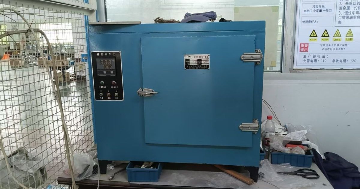
The facility. A climatic test room large enough that the clearance between the test object and the walls and ceiling exceeds 1.0 m, with the equipment raised at least 0.5 m off the floor so ambient air can circulate. Temperature control to within plus or minus 3 K, cycling between 30 degC and 50 degC at a gradient of at least 0.5 K per minute. Precautions are required to stop condensate on the chamber walls and ceiling dripping onto the equipment. The humidification water must have a conductivity of not more than 20 microsiemens per centimetre — so the test reproduces clean condensation, which is precisely why the classification is limited to P0.
The cycle. A 2-hour damp-heat cycle in four zones:
- Zone 1 — rise from 30 degC to 50 degC in 40 minutes, RH above 95%
- Zone 2 — hold at 50 degC for 20 minutes, RH above 95%
- Zone 3 — fall from 50 degC to 30 degC in 40 minutes, humidity uncontrolled
- Zone 4 — hold at 30 degC for 20 minutes, RH above 80%
The period. Each seven-day period is five days energised at rated voltage — Ur between phases, Ur divided by root 3 phase-to-earth — running 60 consecutive damp-heat cycles, followed by two days at approximately 20 degC and 60% RH. The equipment is fully assembled with every component fitted as in service, instrument transformers included, new and clean, earthed as in service. The high-voltage source is monitored continuously so that any disruptive discharge during ageing is detected, with protection operating in under 0.1 s.
| Class 1 (level 1) | Class 2 (level 2) | |
|---|---|---|
| Test periods | 3 | 7 |
| Total elapsed duration | 21 days (504 h) | 49 days |
| Days energised under damp heat | 15 | 35 |
| Damp-heat cycles | ~180 | ~420 |
| Upgrade path | — | Permitted to continue from a passed Class 1 with 4 additional 7-day periods |
The assessment — the part that separates real compliance from paperwork. After ageing, and with the equipment explicitly not cleaned, dried or otherwise treated, it is subjected to the dry 1-minute power-frequency withstand test at its full rated value per IEC 62271-1. Then the temperature is raised to 30 degC and humidity to at least 95% within one hour, held for three hours, and a second dielectric sequence is applied: one phase energised at Ur divided by root 3 for one hour, the other two earthed, then raised to root 3 times Ur for 30 seconds, repeated on each phase. Photographs of any tracking on insulating surfaces must appear in the test report.
That prohibition on cleaning is the heart of it. A panel that survives 180 damp-heat cycles and then holds full rated withstand voltage while still wet, without a wipe-down, has demonstrated something a nameplate cannot. If a supplier offers a "tropicalised" panel, ask whether they hold a 62271-304 report and, if so, which class — and check that the report includes the post-ageing photographs.
The Gap in the Standard: No Test Exists for Polluted Rooms
Here is the limitation that changes how you should approach the problem, and it is stated openly in the specification itself.
Classification under IEC TS 62271-304 is limited to equipment intended for use in a P0 environment — very light pollution. The available classes are C0P0, CLP0 and CHP0. There is no class for CLPL, CHPH or any other combination involving real pollution.
The reason given is candid: existing artificial pollution test procedures were developed for outdoor glass, ceramic and polymeric insulators, and there is no mature testing methodology representative of ageing under polluted indoor service conditions. Annex E proposes a procedure purely to build correlation experience between laboratory ageing and site ageing, not as a basis for certification. Pollution at the site should simply be recorded.
What this means commercially. If your switchroom is genuinely polluted — a cement plant, a smelter, a coastal site with salt aerosol, a mine with diesel particulate, an unsealed room beside a heavy-traffic road — then no manufacturer on Earth can sell you a certificate for that condition, because the test to earn one does not exist. Any supplier claiming otherwise is either describing a different standard or is bluffing.
The engineering answer follows directly from the failure mechanism described earlier. Stage 1 was deposition, and stage 1 is the controllable one. Since you cannot certify the panel against pollution, you have to move the pollution problem out of the panel and into the room and the enclosure:
- Restore P0 conditions inside the room — sealing, filtered pressurised ventilation, airlock entry — and then specify Class 1 or Class 2 against condensation, which is testable. This is the route the standard itself anticipates when it lists "rooms in areas with pollution with precautions against pollution to recover indoor normal service conditions" under P0.
- Or remove the exposed dielectric surfaces altogether by moving to a sealed technology, so that pollution has nothing to settle on that matters.
Either way, the decision belongs in the building design, not in the panel datasheet — which is why it is usually made far too late.
Countermeasures, Ranked by What They Actually Buy You
| Measure | Attacks which stage | Effectiveness | Relative cost | Honest assessment |
|---|---|---|---|---|
| Sealed, filtered, slightly pressurised switchroom | 1 (deposition) | Very high | Medium, civil scope | The highest-leverage measure and the one that restores P0 so the panel can be classified at all. Must be designed into the building. |
| Gas-insulated or solid-insulated switchgear | 1 and 2 | Very high | High capex, often lower total | Removes the exposed dielectric from the equation entirely. See our GIS guide. |
| Correctly sized heaters with hygrostat control | 2 (wetting) | High if sized right | Low | Cheap and effective — but almost always undersized and thermostat-controlled. See the next section. |
| IEC TS 62271-304 Class 1 or Class 2 equipment | 3 and 4 (tolerance) | High | Medium | Proves the design survives condensation. Does not stop condensation happening. |
| Dehumidifier in the switchroom | 2 | Medium | Low capex, ongoing opex | Works while it works. A failed dehumidifier is invisible until the switchgear fails. |
| Higher IP rating on the enclosure | 1 | Medium | Low | Keeps dust out, but a sealed cubicle in a humid room traps moist air and can worsen condensation. Pair with heaters, never alone. |
| Increased creepage distance | 3 | Medium | Medium, adds size | Buys margin against tracking. Does not address the cause, and enlarges the cubicle. |
| Conformal coating on LV and relay boards | 2 | High for electronics | Very low | Should be standard on any tropical order. Ask whether it is. |
| "Tropicalised" with no standard cited | none | Zero | Zero | A marketing word with no defined technical content. Reject it in a specification. |
Anti-Condensation Heater Sizing: The Number Most Panels Get Wrong
Heaters are the cheapest effective countermeasure and the most consistently mis-specified. The physics for a sealed cubicle is a first-order steady-state heat balance:
P = k x A x deltaT
where P is heater power in watts, A is the effective external heat-losing surface area in square metres, deltaT is the temperature rise to be held above ambient in kelvin, and k is the overall heat transfer coefficient — approximately 5.5 W/(m²·K) for a painted sheet-steel enclosure in still air.
Work it through for a typical 12 kV cubicle of 1,000 mm wide, 1,500 mm deep, 2,300 mm high:
- Total external area = 2(1.0 x 1.5) + 2(1.0 x 2.3) + 2(1.5 x 2.3) = 3.0 + 4.6 + 6.9 = 14.5 m²
- Less the floor contact area, effective area is roughly 13 m²
- To hold 5 K above ambient: P = 5.5 x 13 x 5 = 358 W
- To hold 10 K above ambient: P = 715 W
The heater commonly fitted to a cubicle of this size is 50 W. That is around one seventh of what is needed to hold even a 5 K rise. A 50 W heater in a 13 m² enclosure holds roughly 0.7 K, which is thermally indistinguishable from no heater at all.
Three qualifications, because this is exactly where a simple formula gets misapplied:
- Ventilated cubicles change the objective. If the cubicle exchanges air with the room you cannot hold a bulk deltaT at any sane power, and trying to is a waste of energy. The goal becomes keeping the critical surfaces above the local dew point: cable terminations, post insulators, CT and VT surfaces, busbar supports. That means several smaller heaters placed where the dielectric is, not one large heater at the bottom of the panel.
- Control by hygrostat, not thermostat alone. A thermostat switches on cold and off warm. Condensation risk is driven by the dew-point margin, not by temperature, and the worst condensation events happen when warm humid air meets cool metal — conditions in which a thermostat will happily stay switched off. A combined hygrostat and thermostat is a few dollars and is the difference between a working heater circuit and a decorative one.
- The heater must be on when the switchgear is off. The most damaging condensation occurs during outages and shutdowns, when there is no load-loss heating at all. Heater supply should come from a source that survives the equipment being de-energised, and this needs to be stated in the specification because the default wiring frequently does not.
IEC 60890 gives the rigorous method for enclosure temperature calculation; the arithmetic above is a sizing sanity check, not a substitute for it. But it is enough to tell you in thirty seconds whether the heater in a quotation is serious.
Coastal Sites: ISO 9223 Corrosivity Is a Separate Specification
Salt aerosol adds a second, independent problem. Condensation attacks the insulation; salt attacks the steelwork, the fasteners, the hinges and the operating mechanism — and it makes the condensate far more conductive, accelerating every stage of the tracking sequence.
Atmospheric corrosivity is classified by ISO 9223 from C1 (dry, heated interiors) through C5 (very high), with CX added for extreme offshore and industrial atmospheres. ISO 12944 then specifies the matching protective paint systems, with surface preparation and dry film thickness increasing with the category; ISO 12944-9 introduced CX by combining the former C5-I (industrial) and C5-M (marine) categories.
| ISO 9223 category | Typical location | Enclosure specification we would quote |
|---|---|---|
| C1-C2 | Heated indoor, dry rural | Standard powder-coated sheet steel |
| C3 | Urban, inland industrial, low-humidity coastal | Powder coat over zinc-phosphate pretreatment |
| C4 | Industrial areas, coastal with moderate salinity | Aluzinc or hot-dip galvanised substrate plus coating; stainless fasteners |
| C5 | Industrial with high humidity, coastal with high salinity | Multi-coat ISO 12944 C5 system; 316 stainless hardware, hinges and locks |
| CX | Offshore, splash zone, extreme industrial | ISO 12944 CX system or 316L enclosure; sealed technology strongly preferred |
Two points that cost projects money. First, corrosivity category and condensation class are orthogonal: a C5 coating on a panel that has never been condensation-tested still tracks internally, and a Class 2 panel in a plain painted enclosure still rusts through at the plinth. Specify both. Second, the hardware is usually the failure point, not the panel — hinges, door locks, earth studs, gland plates and fasteners are routinely carried over from the standard bill of materials even when the enclosure itself is upgraded. Ask specifically.
Copy-Paste Spec Block for Humid, Tropical and Coastal Sites
Service conditions — humidity, condensation and pollution
Site maximum ambient: _____ degC | 24-hour mean maximum: _____ degC | Minimum: _____ degC
Absolute humidity or dew point (do not state RH alone if ambient exceeds 28 degC): _____
Switchroom: air-conditioned / ventilated / unconditioned — delete as applicable
Expected condensation frequency per IEC TS 62271-304: C0 / CL / CH
Site pollution per IEC TS 62271-304 and IEC TS 60815-1: P0 / PL / PH
Distance from coast: _____ km | ISO 9223 corrosivity category: C1 / C2 / C3 / C4 / C5 / CX
Required from supplier
1. IEC TS 62271-304 classification offered: Class 0 / Class 1 / Class 2 — state the class explicitly; "tropicalised" is not an answer
2. If Class 1 or 2: test report reference, including post-ageing photographs of insulating surfaces
3. If site pollution is PL or PH: written statement of the pollution-control measures assumed at the room level, since no classification test exists for polluted environments
4. Anti-condensation heater rating in watts per cubicle, the assumed deltaT, and the control method (hygrostat required, thermostat alone not accepted)
5. Confirmation that the heater supply remains energised when the switchgear is de-energised
6. Enclosure coating system to ISO 12944 for the stated category, and the material of hinges, locks, fasteners and gland plates
7. Conformal coating on all LV, protection and control boards: yes / no
Item 1 alone changes the conversation with most suppliers. For the rest of the datasheet, see our MV switchgear specification and RFQ guide, and for what gets verified at the factory, our metal-clad switchgear testing standards guide.
Specifying Switchgear for a Humid or Coastal Site?
Send us your ambient temperature range, dew point or absolute humidity, switchroom type, distance from the coast and pollution environment, and we will tell you which IEC TS 62271-304 class is appropriate, what the heater scheme should be, and where a sealed technology would cost less over the life of the installation than repeatedly refurbishing an air-insulated lineup.
We will also tell you plainly if the honest answer is that your room needs fixing rather than your panel — which on genuinely polluted sites it usually is.
Contact NAIJI Electric — medium-voltage switchgear and circuit breakers since 2001, factory direct, 30-60 day delivery, tropical and coastal configurations available.
Related guides: IEC 62271 Standards Explained | Switchgear Maintenance & Testing | Gas-Insulated Switchgear Guide | Metal-Clad Switchgear Testing Standards | Switchgear Altitude Derating