Quick Answer: LV or MV?
Use low voltage (LV) switchgear — at or below 1,000 V — when you are feeding loads directly and total connected load is under roughly 1,500-2,000 kVA with short cable runs. Use medium voltage (MV) switchgear — above 1,000 V, typically 3.3 kV to 40.5 kV — when you need to move power more than about 100-150 metres, when connected load exceeds roughly 2 MVA, when you have motors above 200 kW, or when the utility connection itself is at MV. Most real projects use both: MV upstream of the transformers, LV downstream of them.
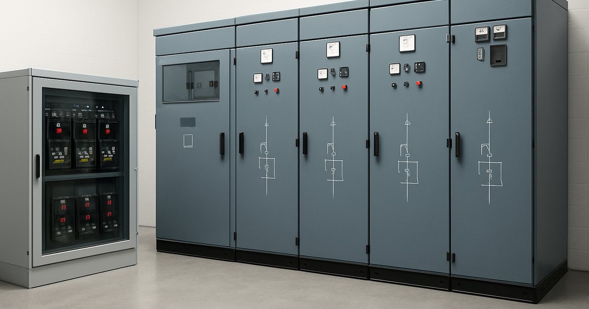
Voltage Classes: Why Three Standards Give Three Answers
Before comparing hardware, settle the vocabulary — because "medium voltage" is defined differently by three authorities, and specifications get written against all three.
| Reference | Low Voltage | Medium Voltage | High Voltage |
|---|---|---|---|
| IEC 60038 / IEC 62271 scope | ≤ 1,000 V AC | > 1 kV, switchgear standards cover up to 52 kV | > 52 kV (IEC 62271-203 onwards) |
| IEEE Std 1585 | ≤ 1,000 V | 1 kV - 35 kV | > 35 kV |
| ANSI C84.1 | ≤ 1,000 V | > 1,000 V to 100 kV | 100 kV - 230 kV |
| Common utility usage (UK, India, AU) | ≤ 1,000 V | Often called "HV" | Transmission only |
The practical consequence: an 11 kV panel can legitimately be called medium voltage switchgear in an IEC specification and HV switchgear in the same client's site rules. We receive enquiries every month asking for "HV switchgear" that turn out to be 11 kV metal-enclosed bays. Always write the number. Our guide to what medium voltage actually means works through the regional naming in more detail.
Standard system voltages you will actually meet:
- LV: 400/230 V and 690 V (IEC world); 480/277 V, 208/120 V and 600 V (North America)
- MV: 3.3, 6.6, 11, 22, 33 kV (IEC world); 4.16, 13.8, 34.5 kV (North America); 10 kV, 20 kV, 35 kV (China and much of Europe)
What Low Voltage Switchgear Actually Is
LV switchgear is a metal assembly containing air circuit breakers (ACBs), moulded case circuit breakers (MCCBs), miniature breakers, contactors, metering and busbars, distributing power at 1,000 V or less directly to loads. The governing standards are IEC 61439-1/-2 for power switchgear and controlgear assemblies, and ANSI/IEEE C37.20.1 for metal-enclosed low-voltage power circuit breaker switchgear in North America.
The defining design constraint is current. Because power equals voltage times current, low voltage means very high amperage: a 2,500 kVA transformer at 400 V delivers 3,608 A on its secondary. That drives everything — busbars are large copper or aluminium bars rated 800 A to 6,300 A, terminations are bolted and torque-controlled, and heat rise becomes the practical limit on how much you can pack into a section.
LV assemblies are graded by form of separation under IEC 61439-2 — Form 1 (no internal separation) through Form 4b (every functional unit and its terminals separated) — which is the LV equivalent of the LSC classification used in MV. Most industrial and data centre specifications call for Form 3b or Form 4b. NAIJI's SLVA grid-standardized low voltage switchgear is built for utility and industrial LV distribution up to 6,300 A. If you are choosing between breaker types inside an LV panel, see our ACB vs MCCB comparison.
What Medium Voltage Switchgear Actually Is
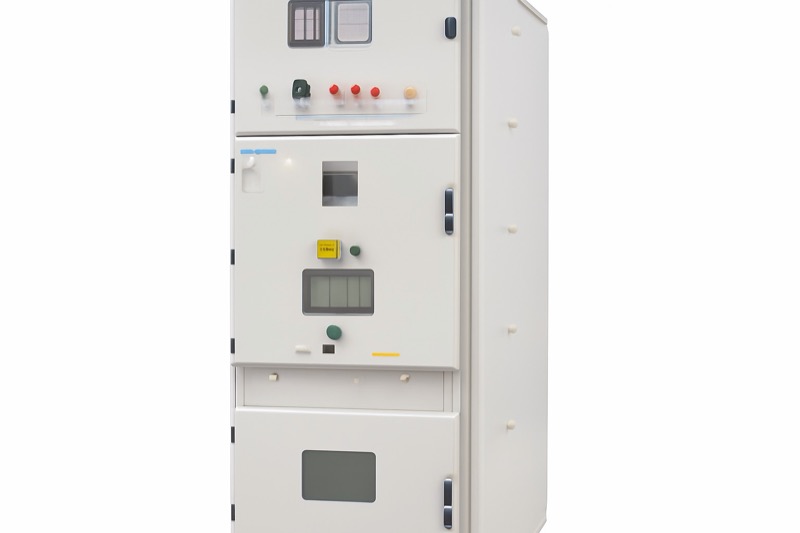
MV switchgear is a compartmented metal assembly containing vacuum circuit breakers, busbars, current and voltage transformers, earthing switches and protection relays, operating above 1 kV. The governing standards are IEC 62271-200 (AC metal-enclosed switchgear and controlgear for rated voltages above 1 kV and up to and including 52 kV) and, in North America, ANSI/IEEE C37.20.2 for metal-clad and C37.20.3 for metal-enclosed interrupter switchgear.
Here the defining constraint is insulation and arc control, not current. A 12 kV bay carries a modest 630-1,250 A in most feeders, but it needs phase-to-earth clearances in the order of 125 mm in air, a lightning impulse withstand of 75 kV, an interrupter that clears 25-31.5 kA in under three cycles, and a tested pressure-relief path for an internal arc. That is why an MV bay is typically 800-1,200 mm wide and 2,200-2,500 mm tall for what may be only a few hundred amps.
NAIJI supplies the ASN3-12 at 12 kV, the ASN2-24 at 24 kV and the ASN1-40.5 at 40.5 kV, all with drawout vacuum breakers and full mechanical interlocking. Classification detail — LSC2B, PM partitions, internal arc codes — is covered in our metal-enclosed switchgear guide.
LV vs MV Switchgear: 14-Point Comparison
| Dimension | Low Voltage Switchgear | Medium Voltage Switchgear |
|---|---|---|
| Rated voltage | ≤ 1,000 V AC (typ. 400/480/690 V) | 3.3 - 40.5 kV (typ. 11/12/24/33 kV) |
| Core standards | IEC 61439-1/-2; ANSI C37.20.1 | IEC 62271-200; ANSI C37.20.2 / C37.20.3 |
| Typical continuous current | 630 - 6,300 A | 630 - 2,500 A (4,000 A in generator bays) |
| Short-circuit withstand | 50 - 100 kA, 1 s | 20 - 40 kA, 3-4 s |
| Main switching device | Air circuit breaker, MCCB, contactor | Vacuum circuit breaker, SF6 or vacuum load break switch |
| Arc interruption medium | Air, with arc chutes and splitter plates | Vacuum (10-4 Pa sealed interrupter) or SF6 |
| Insulation level (BIL) | Not usually specified; 8 kV impulse typical | 75 kV BIL at 12 kV; 125 kV at 24 kV; 185 kV at 40.5 kV |
| Separation classification | Form 1 to Form 4b (IEC 61439-2) | LSC1 / LSC2A / LSC2B, PM or PI (IEC 62271-200) |
| Internal arc reference | IEC/TR 61641 guidance | IEC 62271-200 Annex AA, e.g. IAC AFLR 31.5 kA 1 s |
| Typical section size (W×D×H) | 600-1,000 × 800-1,200 × 2,200 mm | 800-1,200 × 1,500-2,800 × 2,200-2,650 mm |
| Protection | Breaker trip units; some relays on incomers | Numerical relays: 50/51, 50N/51N, 27/59, 87, 49 |
| Operator competence | Qualified electrician | Authorized HV/MV person, permit-to-work regime |
| Maintenance interval | Annual thermographic scan; ACB service ~5 years | Inspection every 5-8 years or 10,000 operations |
| Indicative FOB China per section | $1,800 - $7,000 | $2,800 - $18,000 depending on kV class |
Not sure which level your project needs? Send us your single-line diagram and load list — our engineers will size both options and quote them side by side. Contact NAIJI Electric.
The Real Decision: Where the Crossover Sits
Engineers rarely choose LV or MV on preference. The choice is forced by three numbers: load size, distance, and the largest motor.
1. Load size — the current problem
Current for a three-phase load is I = S ÷ (√3 × V). Run that for one 2,000 kVA load at different distribution voltages:
| Distribution voltage | Current for 2,000 kVA | Copper needed (indicative) | Relative I²R loss |
|---|---|---|---|
| 400 V | 2,887 A | 6 × 300 mm² per phase, or busduct | Baseline (100%) |
| 3.3 kV | 350 A | 1 × 120 mm² per phase | ≈ 1.5% |
| 11 kV | 105 A | 1 × 35 mm² per phase | ≈ 0.13% |
| 33 kV | 35 A | 1 × 25 mm² per phase (insulation-driven) | ≈ 0.015% |
Loss falls with the square of the current, so moving from 400 V to 11 kV cuts conductor losses by a factor of roughly 750 for the same power. That is why the copper bill, not the switchgear bill, usually decides the architecture on large sites.
2. Distance — the voltage drop problem
Voltage drop is proportional to current times length. Commonly applied design limits are 3% on a branch circuit and 5% total in NEC practice, and around 4% under IEC 60364-5-52 Annex G guidance. At 400 V those limits are consumed within roughly 80-150 m on a heavily loaded feeder; at 11 kV the same physical cable can run several kilometres. Rule of thumb from our project work: if a feeder is longer than 150 m and larger than 500 kVA, price the MV option before committing.
3. Largest motor
Motors up to about 200 kW are comfortably fed at 400 V. Between 200 kW and 400 kW it is a genuine trade-off. Above roughly 400-500 kW, MV motors at 3.3 kV or 6.6 kV win on starting current, cable size and motor efficiency — and then you need MV switchgear or a vacuum contactor unit to feed them. See our note on MV motor control with VFDs and soft starters.
Most Projects Are Not LV or MV — They Are Both
The standard architecture on any site above about 1 MVA looks like this:
- Utility incomer at MV (11 kV / 13.8 kV / 33 kV) into a ring main unit or an MV incomer bay with metering
- MV switchgear lineup — incomer, bus section, and one feeder bay per transformer, generator and MV motor
- Distribution transformers, typically 630-2,500 kVA, stepping MV down to 400 V or 480 V
- LV switchgear lineup per transformer — main ACB, bus tie, and outgoing MCCB or ACB feeders
- Final distribution boards and MCCs at the loads
The engineering question is therefore not "LV or MV" but how far down into the site MV should reach before you transform. Push the transformers closer to the loads and you buy more MV bays but far less LV copper. Our MV power distribution system design guide works through radial, loop, primary selective and secondary selective topologies with cost consequences, and the switchgear lineup design guide covers how many bays a lineup actually needs.
Data Centres: A Worked Example of the Hierarchy
Data centres show the split clearly because the reliability requirement forces redundancy at both levels.
| Level | Equipment | Typical rating | Redundancy |
|---|---|---|---|
| Utility / MV | MV switchgear lineup, ring main units | 11-33 kV, 1,250-2,500 A, 25-31.5 kA | 2N incomers, bus tie |
| Generation | MV generator breaker bays | 11 kV, 2,000-4,000 A | N+1 or 2N gensets |
| Transformation | Cast resin unit substation transformers | 1,000-2,500 kVA | One per block, 2N feeds |
| LV distribution | LV switchgear, UPS input/output boards | 400/480 V, 2,000-6,300 A | 2N with static transfer switches |
| Rack level | PDUs, busway | 400 V / 415 V, 100-800 A | Dual corded A/B |
The trend on hyperscale campuses above 10 MW is to push MV deeper — feeding MV directly to block-level unit substations rather than running LV busduct across the building. That grows the MV bay count and shrinks LV copper. Detail in our MV switchgear for data centres guide.
Cost, Lead Time and Total Installed Price
Equipment price is only part of the picture, but here are the indicative FOB China numbers we quote in 2026, per section, at 31.5 kA:
| Assembly | Typical section | Indicative FOB price | Standard lead time |
|---|---|---|---|
| LV switchgear (Form 3b/4b) | Feeder section, MCCB outgoers | $1,800 - $4,000 | 20 - 30 days |
| LV switchgear (Form 4b) | Incomer, 4,000 A ACB + metering | $4,000 - $7,000 | 25 - 35 days |
| MV metal-enclosed, 12 kV | Feeder bay with VCB | $2,800 - $6,500 | 25 - 40 days |
| MV metal-enclosed, 24 kV | Feeder bay with VCB | $5,000 - $12,000 | 30 - 45 days |
| MV metal-enclosed, 40.5 kV | Feeder bay with VCB | $8,000 - $18,000 | 35 - 50 days |
| MV gas-insulated (GIS), 12 kV | Feeder bay, compact | $6,000 - $14,000 | 35 - 50 days |
Two things that surprise buyers comparing quotations:
- Protection relays can be 20-35% of an MV bay price. A specification that names a European relay brand roughly doubles the relay line item versus a compliant Chinese or Korean numerical relay. Decide deliberately — see our protection relay selection guide.
- LV price scales with amperage, MV price scales with kV. Doubling LV current roughly doubles the busbar cost; doubling MV voltage roughly doubles the whole bay because clearances, bushings and insulation all grow.
MOQ is flexible — we ship single bays for retrofits as well as complete lineups. All prices are indicative and confirmed against your single-line diagram and ratings.
Safety and Operating Regime: The Difference Nobody Budgets For
The operational difference between LV and MV is bigger than the hardware difference. LV panels are switched by qualified electricians as routine work. MV switching requires an authorized person, a permit-to-work, documented isolation and earthing, and in most jurisdictions two-person operation.
- Arc flash: incident energy is assessed with IEEE 1584-2018 at both levels. LV boards frequently produce the higher incident energy at the working position because arcs at 400-600 V can be sustained in the enclosure, while MV bays are typically protected by tested internal arc containment and venting rather than PPE alone.
- Earthing: MV bays carry an integral earthing switch with a making capacity; LV isolation is normally proved with a tester and portable earths. Detail in our earthing and grounding guide.
- Interlocking: MV drawout construction enforces the sequence mechanically — you cannot rack in against a closed earth switch. See arc flash protection in switchgear.
10-Point Selection Checklist
- Confirm the utility supply voltage and whether the connection point is LV or MV
- Total the connected load in kVA and identify the largest single motor
- Measure the longest feeder run from the intake to the furthest load centre
- Get the utility fault level in kA — this sets the short-circuit rating of everything downstream
- Decide the distribution level: if load > 2 MVA or run > 150 m, price MV
- Choose the standard system — IEC or ANSI — and do not mix requirements in one specification
- State the separation class: Form 3b/4b for LV, LSC2B PM for MV
- State the internal arc requirement with duration (e.g. IAC AFLR 31.5 kA 1 s)
- Define relay functions and communication protocol (IEC 61850, Modbus, DNP3)
- Check the room: door width, floor loading, cable entry direction, arc venting path
Working through a full enquiry document? Our MV switchgear specification and RFQ guide gives a fill-in data sheet, and the short-circuit rating calculation guide covers point 4 in detail.
Why Buyers Source Both Levels From One Factory
NAIJI Electric manufactures medium voltage switchgear from 12 kV to 40.5 kV, gas-insulated switchgear, indoor and outdoor vacuum circuit breakers, and grid-standardized low voltage switchgear in one plant. Sourcing the MV lineup, the transformer-side connections and the LV lineup from a single manufacturer removes the interface problems that cost weeks on site: matching busbar centres, cable entry directions, control voltage, relay protocol and terminal numbering all get resolved on one set of drawings.
- Type-tested designs to IEC 62271-200 and IEC 61439 with third-party reports available
- 12 kV to 40.5 kV MV bays, 6,300 A LV assemblies, single-bay MOQ for retrofits
- Standard lead time 25-45 days; factory acceptance test with client witness on request
- Export documentation, CE marking and spare parts packages included in quotation
Bottom Line
LV switchgear solves a current problem; MV switchgear solves an insulation problem. Below about 1,500-2,000 kVA with short runs, LV alone is cheaper and simpler to operate. Above that, or beyond about 150 m, MV distribution pays for itself in copper and losses before you count reliability. On almost every industrial site, plant, hospital or data centre above 1 MVA, the correct answer is a properly sized MV lineup feeding transformers that feed properly sized LV lineups — and the engineering value is in deciding where that boundary falls.
Get an LV & MV Switchgear Quotation →
Related guides: What Is Medium Voltage? | Metal-Enclosed Switchgear Guide | MV Switchgear for Data Centres | Switchgear vs Switchboard | MV Distribution System Design | Types of Electrical Switchgear