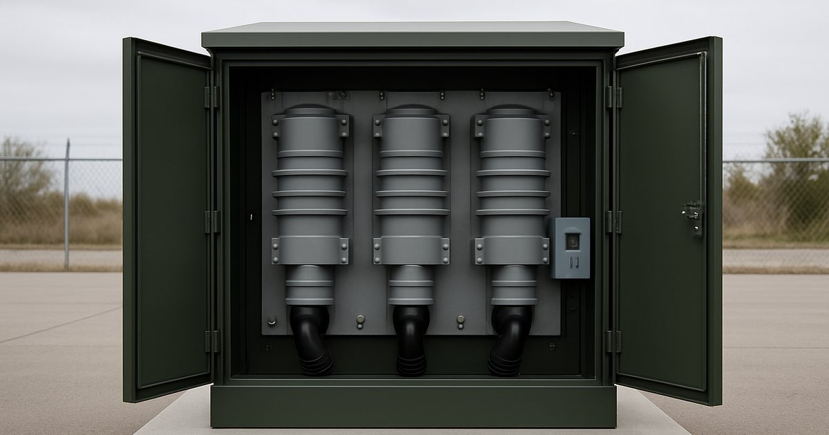
Quick Answer: What Is a Vacuum Fault Interrupter?
A vacuum fault interrupter (VFI) is a resettable overcurrent protective device for 15-38 kV underground distribution. It detects a fault through built-in current transformers, trips through an electronic (or older hydraulic) control, and extinguishes the arc inside a sealed vacuum interrupter. You find VFIs in pad-mounted switchgear, in VFI transformers and in vault or submersible units, where they do the job power fuses used to do — except they can be reset instead of replaced, can trip all three phases together, and have adjustable time-current curves. Typical ratings: 15.5/27/38 kV, 95/125/150 kV BIL, 200-600 A continuous, 12.5-25 kA interrupting, tested to IEEE C37.60 (harmonized with IEC 62271-111).
This guide explains how a VFI works, how to read its ratings, when a fuse is still the better answer, how to set the trip curve on a transformer tap, what the IEC equivalent is if you buy outside North America, and what it costs. We write it as a vacuum switchgear manufacturer — our vacuum circuit breakers and C-GIS panels do the same job under IEC standards — so the numbers come from our own quotes and test bays, not from a brochure.
How a Vacuum Fault Interrupter Works
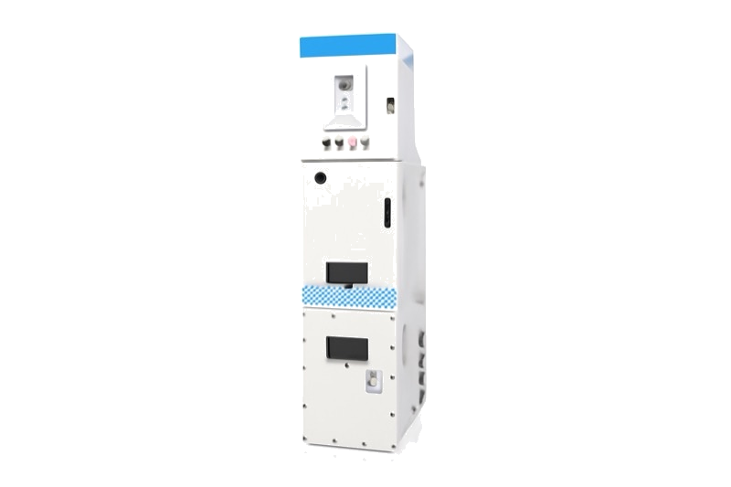
Every VFI has the same four stages between the fault and the dead circuit:
- Sensing. Current transformers on each phase (typically 600:1 or 1000:1 on 600 A ways) feed the control. On self-powered designs the same CTs also harvest the energy the control needs, so no battery or auxiliary supply is required.
- Decision. The control compares phase and ground current against the programmed time-current curve (TCC). Older VFIs use a hydraulic or series-trip coil with fixed curves; modern ones use a microprocessor control with selectable curves, instantaneous elements and separate ground-trip settings.
- Release. The control fires a trip solenoid or magnetic actuator, which releases a stored-energy spring mechanism. A three-phase VFI opens all three vacuum bottles through one mechanism; a single-phase design has one mechanism per phase.
- Interruption. The contacts part inside the vacuum bottle. The arc burns in metal vapour from the CuCr contacts and goes out at the next current zero — within half a cycle of contact separation (8.3 ms at 60 Hz). The contact gap needed to hold off recovery voltage is only about 8-12 mm at 15-27 kV class, which is why VFI modules are so compact.
Total clearing time is typically 3-5 cycles (50-85 ms at 60 Hz) for an electronic control with the instantaneous element active. That is slower than a current-limiting fuse on a bolted fault — more on that below — but much faster than a time-delayed fuse at moderate fault levels.
The VFI then stays open. Unlike a distribution recloser, it does not try to reclose, because faults on underground cable (insulation breakdown, dig-ins, failed splices) are almost always permanent. Reclosing onto them only adds damage.
VFI Ratings Explained: What the Nameplate Tells You
North American VFIs are rated and type-tested to IEEE C37.60, which covers overhead, pad-mounted, dry-vault and submersible reclosers and fault interrupters above 1 kV and up to 38 kV. Its duty-cycle test is demanding — Eaton summarizes it as 116 fault-interrupting operations at various percentages of the rated symmetrical short-circuit current. The pad-mounted switchgear assembly around the VFI is covered by IEEE C37.74, and the enclosure by IEEE C57.12.28 (mild steel) or C57.12.29 (stainless steel for coastal sites).
| Rating | 15 kV class | 25 kV class | 35 kV class | What it means for you |
|---|---|---|---|---|
| Maximum voltage | 15.5 kV | 27 kV | 38 kV | Must exceed your system maximum (e.g. 13.2 kV nominal needs 15.5 kV) |
| BIL (lightning impulse) | 95 kV | 125 kV | 150 kV | Coordinate with arrester protective level; add margin at riser poles |
| Continuous current | 200 / 600 A | 200 / 600 A | 200 / 600 A | 200 A for transformer taps, 600 A for main loop ways |
| Interrupting (sym.) | 12.5 - 25 kA | 12.5 - 25 kA | 12.5 - 25 kA | Must exceed the available fault current at that bus — calculate it, do not guess |
| Momentary / fault-close | 20 - 40 kA asym. | 20 - 40 kA asym. | 20 - 40 kA asym. | Checks the VFI survives closing onto a fault |
| Test standard | IEEE C37.60 / IEC 62271-111 (device); IEEE C37.74 (assembly) | Ask for the type-test report, not a declaration | ||
12.5 kA symmetrical is the most common rating for oil-insulated VFIs. Molded solid-dielectric designs go higher — ABB publishes 25,000 A symmetrical from 5 to 38 kV for its Elastimold molded vacuum fault interrupters. If your available fault current is above 12.5 kA, check the rating before you check the price; our short-circuit rating calculation guide walks through the numbers.
Insulation Options: Oil, SF6, Solid Dielectric or Air
The vacuum bottle does the interrupting in every design. What differs is the insulation between phases and to ground — and that choice drives weight, footprint, submersibility, and regulatory risk.
| Insulation | Typical products | Strengths | Watch-outs |
|---|---|---|---|
| Mineral oil / natural ester (FR3) | Oil-filled VFI switchgear, VFI transformers | Long field history, low cost, compact | Oil containment, fire-point rules near buildings; ester raises the fire point above 300 °C |
| SF6 gas | Gas-insulated pad-mount and vault switchgear | Very compact, sealed, submersible | GWP 23,500; EU F-gas Regulation 2024/573 bans new SF6 MV switchgear up to 24 kV from 2026 |
| Solid dielectric (epoxy / EPDM) | Molded VFI modules, solid-insulated RMUs | No gas or oil, submersible, low maintenance | Partial-discharge quality depends on casting process; 15-25% price premium |
| Air + vacuum | Live-front or dead-front air pad-mounts, indoor panels | Visible, easy to inspect, no insulating medium to manage | Largest footprint; sensitive to contamination and condensation |
If your project is in the EU or you want to avoid the SF6 question entirely, see our EU F-gas and SF6-free compliance guide. Our GSN3-12 C-GIS, for example, uses nitrogen insulation with vacuum switching, so there is no F-gas to report or recover.
VFI vs Fuse vs Recloser vs Circuit Breaker
This is the decision most buyers are actually making. A VFI is not automatically "better" than a fuse — it is better in specific situations.
| Criterion | Power / CL fuse | Vacuum fault interrupter | Recloser | Relay + vacuum circuit breaker |
|---|---|---|---|---|
| After a fault | Replace fuse (crew visit) | Reset (local or remote) | Auto-recloses 1-3 times, then locks out | Reset / reclose via relay |
| Three-phase trip | No — single-phasing risk | Yes (ganged) or selectable single-phase | Yes, or single-phase on some models | Yes |
| Adjustable curve | No — change fuse size | Yes, programmable TCC + ground trip | Yes, full relay functions | Yes, full relay functions |
| Speed on bolted fault | Fastest (CL fuse < 1/2 cycle, limits let-through) | 3-5 cycles | 3-5 cycles | 3-6 cycles incl. relay |
| Ground-fault sensitivity | Poor (sized for phase load) | Good — independent ground setting | Good | Best |
| Best location | Small transformer taps | Underground loops, pad-mount taps | Overhead feeders | Substations, industrial incomers |
| Standard | IEEE C37.41/.46/.47, IEC 60282-1 | IEEE C37.60, IEC 62271-111 | IEEE C37.60, IEC 62271-111 | IEC 62271-100 / IEEE C37.04 |
| Relative device cost | Lowest | Medium | Medium-high | Highest |
Three rules of thumb from our quoting desk:
- Three-phase motor loads (pumps, compressors, chillers) behind the device? Use a VFI or breaker. One blown fuse leaves the motor running on two phases, overheating it within minutes if the motor protection is weak.
- High available fault current and arc-flash concerns at a small tap? A current-limiting fuse's let-through limiting is hard to beat. See our arc flash protection guide.
- Overhead line with mostly temporary faults? That is recloser territory, not VFI — our recloser vs sectionalizer comparison covers the overhead side.
Choosing between fuse-switch and breaker protection for a project?
Send us the transformer sizes, available fault current and single-line diagram. Our engineers will recommend the protection function per way and quote both options side by side — usually within 24 hours.
Request a Quote for This Configuration →Setting the Trip Curve: A Worked Transformer Example
The biggest advantage of an electronic VFI — adjustable protection — is also where most commissioning mistakes happen. Here is how we set a VFI protecting a 1,000 kVA, 13.2 kV pad-mounted transformer.
| Step | Calculation | Result |
|---|---|---|
| 1. Full-load current | 1,000 kVA ÷ (√3 × 13.2 kV) | 43.7 A |
| 2. Magnetizing inrush point | 12 × FLC for 0.1 s (common ANSI practice) | 525 A at 0.1 s — curve must sit above this |
| 3. Phase minimum trip | ~2-3 × FLC, allowing for cold-load pickup | 90 - 130 A |
| 4. Ground minimum trip | Independent of phase; above normal unbalance | 20 - 40 A typical |
| 5. Transformer damage curve | IEEE C57.109 through-fault curve | VFI curve must sit left of (faster than) it |
| 6. Coordination margin | Coordination time interval to upstream feeder relay | 0.2 - 0.3 s at max fault on this bus |
With a fuse you would be choosing between, say, a 65E and an 80E link and living with whatever curve that gives you. With a VFI you place the curve exactly in the window between inrush and damage, and set ground protection separately — which is where most of the reliability gain comes from, because a phase fuse sized for 44 A load will barely see a 60 A high-impedance ground fault. For relay-side coordination above the VFI, see our medium voltage protection relay guide.
Single-phase or three-phase trip? Residential loops serving single-phase transformers are often set to single-phase trip, so a fault on one phase does not drop customers on the other two. Anything feeding three-phase motors should be three-phase (ganged) trip. Many controls allow both, selectable per way — specify which one you want in the RFQ.
The IEC Equivalent: RMU and C-GIS Circuit-Breaker Functions
"VFI" is North American terminology. If you buy to IEC standards — most of Asia, the Middle East, Africa and Latin America — the same job is done by the circuit-breaker function (V) of a ring main unit or a C-GIS panel, and the fused alternative is the fuse-switch combination (F) under IEC 62271-105. A "2L + 1V" RMU is the IEC cousin of a pad-mount with two loop switches and one VFI tap.
| North American (IEEE) | IEC equivalent | Typical IEC rating |
|---|---|---|
| Pad-mounted switchgear, loop switch way | RMU load-break switch function (L) | 12/24 kV, 630 A |
| Fused way (power fuse / CL fuse) | Fuse-switch combination (F), IEC 62271-105 | 12/24 kV, 125 A max fuse |
| Vacuum fault interrupter way | Vacuum circuit-breaker function (V), IEC 62271-100 | 12/24 kV, 630 A, 20-25 kA |
| VFI control (self-powered) | Self-powered protection relay (50/51, 50N/51N) | CT-powered, no auxiliary supply |
| IEEE C57.12.28 enclosure | IEC 62271-200 LSC / IAC classification | IAC AFL 20 kA 1 s typical |
In IEC practice the fuse-switch is usually accepted for distribution transformers up to roughly 1,000-1,250 kVA at 10-12 kV (utility practice varies); above that, or wherever a relay, remote trip or frequent faults are involved, the V function is specified. Our RMU types comparison and compact substation design guide show how these functions are combined in practice.
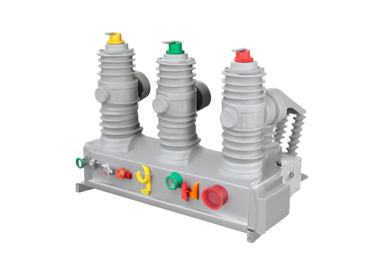
A straight answer on scope: NAIJI builds IEC-rated vacuum switching equipment — the GSN3-12 C-GIS (12 kV, up to 40 kA), the ASN550 compact metal-enclosed switchgear, indoor vacuum circuit breakers for panel builders, and the ZW32-12 outdoor VCB for overhead taps. These are type-tested to IEC 62271-100/-200, not listed to IEEE C37.60. If your utility mandates C37.60 listing for pad-mounted VFIs, we will tell you that at the enquiry stage rather than after the drawings.
What a VFI Costs — and When It Pays Back
Buyers rarely find prices published for VFIs, so here are our indicative FOB China figures for the IEC-equivalent configurations, consistent with the pricing in our RMU manufacturer guide:
| Configuration (12 kV) | Indicative FOB China | Lead time |
|---|---|---|
| 3-way SF6 RMU, 2L + 1F (fuse-switch tap) | $2,000 - $4,000 | 20 - 30 days |
| 3-way RMU, 2L + 1V (vacuum breaker tap, self-powered relay) | $4,000 - $8,000 | 25 - 35 days |
| Adding a V function instead of an F function (per way) | +$1,500 - $3,000 | — |
| Motorized operation + communicating control (per way) | +$500 - $1,500 | +5 - 10 days |
| Solid-insulated / SF6-free version | +15 - 25% | +5 - 10 days |
| 12 kV gas-insulated feeder panel with VCB | $6,000 - $14,000 | 35 - 50 days |
MOQ is one unit for catalog configurations. Prices move with copper, the CT/relay brand you specify and the classification codes (IAC, LSC) — send your data sheet for a firm figure.
Payback, with your own numbers. The extra $1,500-$3,000 for a breaker function is recovered by avoided fuse events. A simple model: payback (years) = extra cost ÷ (fault events per year × cost per fuse event). If a fuse event costs you $1,000 in fuses, crew time and truck roll, and the tap sees two events a year, a $2,500 premium pays back in about 15 months — before counting the value of the outage minutes. On a tap that blows a fuse once every five years, the fuse is the better investment. Run the model per circuit, not per project.
How to Specify a VFI (or V-Function) in Your RFQ
Most re-quotes we issue are caused by missing information, not by price. Include these ten items and suppliers can quote like-for-like:
- Standard system: IEEE C37.60 / C37.74 or IEC 62271-100 / -200 / -111
- Rated and maximum system voltage, frequency, BIL
- Continuous current per way (loop vs tap)
- Available fault current at the installation bus (kA sym, X/R)
- Insulation medium: oil, natural ester, SF6, solid, air — and any F-gas restriction
- Control type: self-powered electronic, relay model preference, curve families required
- Trip mode: three-phase ganged, single-phase, or selectable
- Operation: manual hot-stick, motorized, remote (protocol: DNP3 / IEC 60870-5-104 / Modbus)
- Enclosure: pad-mount steel/stainless, IP rating, IAC classification, submersible requirement
- Site conditions: altitude, ambient range, pollution level, flood exposure
Our full MV switchgear specification and RFQ template has a copy-paste data sheet with these fields and 16 more.
Bottom Line
A vacuum fault interrupter trades a higher upfront price for three things a fuse cannot give you: reset instead of replacement, three-phase tripping, and a trip curve you can actually place between transformer inrush and damage. It earns its premium on underground loops, three-phase loads and circuits that see repeated faults; a current-limiting fuse still wins on small, rarely faulted taps and where let-through limiting matters most. Outside North America, specify the same function as the vacuum circuit-breaker (V) way of an RMU or C-GIS — and compare suppliers on type-test reports, not brochures.
Request a Quote for Breaker-Protected RMU / C-GIS →
Related guides: Vacuum Interrupter Guide | Distribution Recloser Guide | Ring Main Unit Guide | MV Protection Relay Guide | SF6 Load Break Switch Guide | IEC 62271 Standards Guide